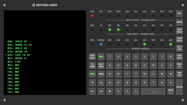
LEDs PURPOSE
| LED | Purpose |
|---|---|
 |
Address register. Displays a current memory address of the content that can be changed (is analogous to the status of the address bus). During program execution displays the contents of the Instruction Pointer IP. |
 |
display the status of the Data Input register DI in the ‘DI view’ mode (the DI LED lights up). If the DI is off, DI0 - DI7 show the status of a memory cell addressed by AD0 - AD7. |
 |
display the status of the Data Output register DO. Used to display the calculation results. In the ‘Debug’ mode DO0 - DO7 can display the contents of the Accumulator. (In this case, the ACC LED is turned on). |
 |
indicates that the device is executing a program. Lights up after pressing the RUN/STOP key. |
 |
indicates that DO0 - DO7 LEDs are in the Accumulator status mode. It’s used only in the ‘Debug’ mode when the DO/A/<-- key is pressed. |
 |
indicates that DI0 – DI7 LEDs are displaying the status of the DI register. The DI is usually used for data input. |
 |
lights up red when the ‘HALT’ instruction is executed. HALT temporarily pauses the program execution until the ENTER key is pressed. (Since the computer is in the program execution process, the RUN is also on). Lights up yellow when the INKBD instruction is executed. |
 |
lights up when the machine is in the ‘Debug’ mode. |
 |
lights up if the machine is in the Binary Data Input mode. |
KEYS PURPOSE
| Key | Purpose |
|---|---|
 |
used to enter data into the address register, or into the memory cell addressed by the AD register, or into the Data Input register DI. If the ‘Binary Input’ mode is set (the BIN LED is on), these keys affect the status of the AD0 – AD7 or DI0 - DI7 registers located above them, (depending on key pressed before: SLCT ADR / SAVE DATA / SAVE DI). When one of the keys is pressed, the value within the corresponding address bit AD0 – AD7 or data bit DI0 - DI7. is inverted. These keys are analogous to the toggle switches that ‘real programmers’ used to enter data, programs to computer memory. If by pressing the BIN/HEX key the Hexadecimal Input mode is set (the BIN is off), the keys 0 – 7 are used as the first 8 keys to enter the value in hexadecimal format. In many modern computers, including the PC series, the conventional order of writing numbers in the binary system is from left to right, from high bits to low bits. Thus in the Calculator, the order of keys from 0 to 7 on the keyboard is not conventional. This is done so that each key is located directly under the LED the value it changes. |
 |
used to enter data in hexadecimal format if the ‘Hexadecimal Input’ mode is set (the BIN LED is off). The first press of one of the keys sets the upper four bits, the second press sets the value of the lower four bits of the data. |
 |
Keyboard. Used to input instructions in Assembly language. In addition, these keys return the code of the pressed keys. (See Input / Output Instructions). |
 |
‘Binary / Hexadecimal input’. If the ‘Binary Input’ mode is set (the BIN is on), the keys 0 - 7 change the status of the registers AD0 – AD7 or DI0 - DI7 located above them (depending on the key pressed before: SLCT ADR / SAVE DATA / SAVE DI). If the ‘Hexadecimal Input’ mode is set (the BIN LED is off), keys 0 - F are used to enter a value in 16-hex format. |
 |
The ‘Backspace’ key deletes a previous character entered in the Assembly instructions editing mode (ASM -> SAVE DATA).
In other cases, pressing this key switches the DO0 - DO7 LEDs to the Accumulator contents display mode. (ACC LED turns on). Pressing the key again returns DO0 - DO7 to the DO register display mode (ACC turns off). |
 |
If the mode is on (DI LED lights up) DI0 - DI7 display the contents of the Data Input register. If the mode is off, DI0 - DI7 LEDs always display the contents of the memory cells addressed by AD0 - AD7. |
 |
by pressing this key, the Calculator switches to the Address Input mode. (AD0 - AD7 LEDs are involved). Address can be:
If the ‘Di View’ mode is off (DI LED is off), then DI0 - DI7 LEDs display the status of a memory cell addressed by AD0 – AD7. Thus, you can always view the contents of a memory cell at a given address. |
 |
end of data input or an address input (depending on the previously pressed SLCT ADR / SAVE DATA / SAVE DI), writing a value to a specified register. For instance, if SLCT ADR key was previously pressed, a value is written to the adress register. |
 |
In the ‘MEM’ mode: by pressing this key Calculator switches to the mode of entering data to addressed memory cell (DI0 - DI7 LEDs are involved). Address can be:
In this case, by pressing the ENTER key a value displayed by DI0 - DI7, LEDs is written to the memory cell addressed by AD0 - AD7. Note! For convenience of entering the next instruction, at the end of saving data a value of the address register automatically increments by 1. Exiting the SAVE DATA mode depends on the ‘EXIT SAVE DATA BY ENTER’ option set in the Settings. It can be done either by the ENTER or by pressing the SAVE DATA again. In the ‘ASM’ mode: by pressing this key Calculator switches to the Assembly instructions editing mode. To go to the next instruction press the ENTER key. In this case, a value of the address register automatically increments by the number of bytes of the entered instruction. To exit the mode press SAVE DATA again. |
 |
writing data to the DI register. Pressing the ENTER key writes the data to the Data Input register DI. At the end of the SAVE DI program a value of the address register does not change. |
 |
writing a program (essentially a memory dump) to a virtual medium. After pressing this key the program name is entered. By pressing the ENTER a program is written to a file. |
 |
reading a program (essentially a memory dump) from a virtual medium into memory. After pressing the key, a program name is entered. By pressing the ENTER a program is reading from a file. |
 |
program start / stop. Run a program starting from the current address AD. If at the time of start the machine was in the ‘Debug’ mode, it exits the mode. When starting, the RUN LED lights up. Stops the program if it was previously launched. |
 |
switch the Calculator to ‘Debug’ mode - step-by-step execution of instructions. At the time, the DEBUG LED lights up. In this mode, the instructions are executed step by step. To step forward use the key. To exit the mode press the DBG key or the RUN/STOP key. |
 |
display on the screen the memory cell status. The mode allows to observe how a values within memory cells are changing during program execution. 
|
 |
display the Instruction Reference on the screen. Pressing the A - Z keys displays an instruction list starting with a corresponding letter, and a brief description of an instructions. To exit the mode, press any function key. |
 |
Switch to the Assembly instructions display mode. In this case, in a row the following is displayed:
In this mode, you can edit the instruction by writing its name from the keyboard after pressing the SAVE DATA key. |
 |
Enter the App Menu. Selecting modes: operation, settings, or reference. |
 |
Exit the App. Caution! Before exiting, save your work to a file using the SAVE PROG key. (After confirming the exit, the data is not saved automatically.) |
DOWNLOAD THE MANUAL
You can download the guide in different formats from the links below:
PDF A4Buy calculator
Use the Calculator on various types of devices including smartphones, tablets and PCs. It will be available soon at the following App stores:
To purchase the Calculator, visit one of the stores